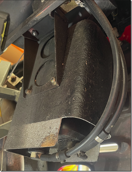
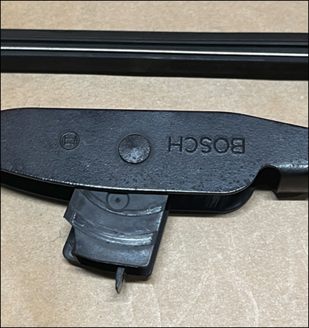
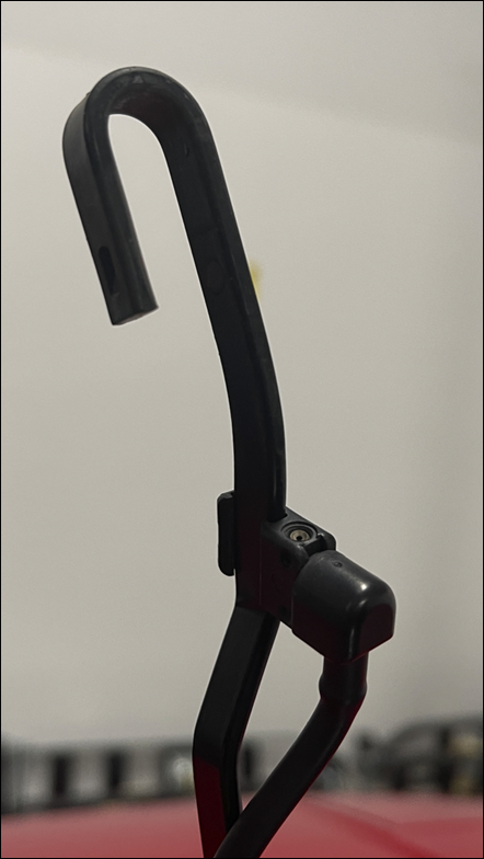
Yes, but what type of screw?

image

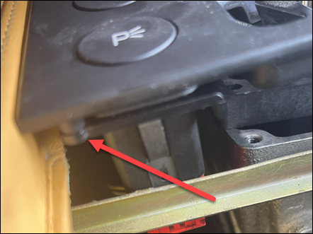
Yet another problem that surfaced recently was the buttons in the centre console being pushed through because the screws that hold them to the frame have come loose. I pulled the console apart and was able to identify the location of one of the missing screws as shown above.

I’ve managed to track down that the part number of the screw in question is 15900270 but it is simply identified as a ‘Screw’, which is not very helpful to me. I need to know two major dimensions, the length and the gauge. If I get a screw that is too long I’ll pierce the face of the frame with the tip. If I get one with the wrong gauge (width) then I’ll ruin the housing it screws into.

So, I’m going to have to take punt that one of these three does the trick:

4G x 6.5mm

6G x 6.5mm

8G x 6.5 mm

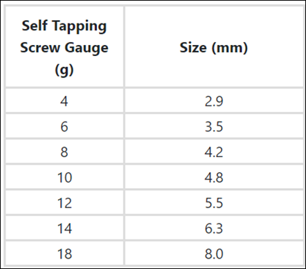
Turns out that the width of a screw is known as the gauge and the conversion table from imperial (gauge) to mm looks like:

image

Thus, what I’ll try (all in mm is)

2.9mm (w) x 6.5mm (l)

3.5mm (w) x 6.5mm (l)

4.2mm (w) x 6.5mm (l)

I did my best to measure the housing that the screw will go into and i got:

4.7mm (w) x 9mm (l)

so my best guess, at least initially will be the

3.5mm (w) x 6.5mm (l)

but I’ve had to order 100 of all three types just so I have them on hand. Annoying that I need just one screw and have to buy 300 to try and find that one right screw. Livin’ the dream.

Hopefully, the ordered replacement screws arrive soon and I can try and fix the button mount and get the console back together. Then, I can decide what to ultimately do with the car.
This may be the end

image

It is with regret that I report that my ownership of a Ferrari F355 maybe at an end. The ‘low power’ issue continues to plague that car and the ownership experience is no longer enjoyable.

After the recent major engine out service, where the charcoal cannister was also replaced, problems started again to surface a few weeks afterwards. The car became harder to start and when it did the revs would start low and them increase. Later on the revs wouldn’t increase and the car would remain in ‘low power’ mode. There are no warning lights on the dash, just a car which struggles to get up any incline.

This all came to head over the last weekend when I headed to Bathurst for the 12 hour race. I knew there was a risk that things would fail, but given the intermittent nature of the problem I felt I needed to force the issue to see the result. Unfortunately, just after I got the car over the mountain range and into Lithgow it struggled to actually start and again had no power.

I let it cool, removed the fuel cap, reset the battery and did everything I could think of, but again now power. I therefore decided to abandon the trip to Bathurst and try and limp the car home. This meant I had to limp the car up a 1 in 8 gradient back up the mountain via Victoria pass! Painful to say the least.

Of course, half way home, the car resumed normal mode and ran like a dream. To top things off, the button on the centre console have dropped through as the screws holding them have also come loose and now the buttons hang loose inside the console near the gear stick.

In short, this ‘low power’ issue has continued now for over two years and there is no solution in sight. I am hesitant to keep throwing money at something that has no path to a reliable solution. It seems to come to randomly changing parts.

I appreciate that intermittent issues can be hard to find and resolve, especially if you can replicate issue on demand. I get it, but I don’t think I can keep going through the discomfort of taking the car out and wondering whether it will fall back into ‘low power’ mode and I’ll have to stress and get it back.

Maybe this the end of my relationship the F355?

Radiator Fan fuses

After recently having an issue with a blown radiator fuse in my F355 I thought it would be a good idea to car some spares with me. I also wanted to review where the fuse box was located. I did some searching but didn’t find anything straight forward. So here it is.

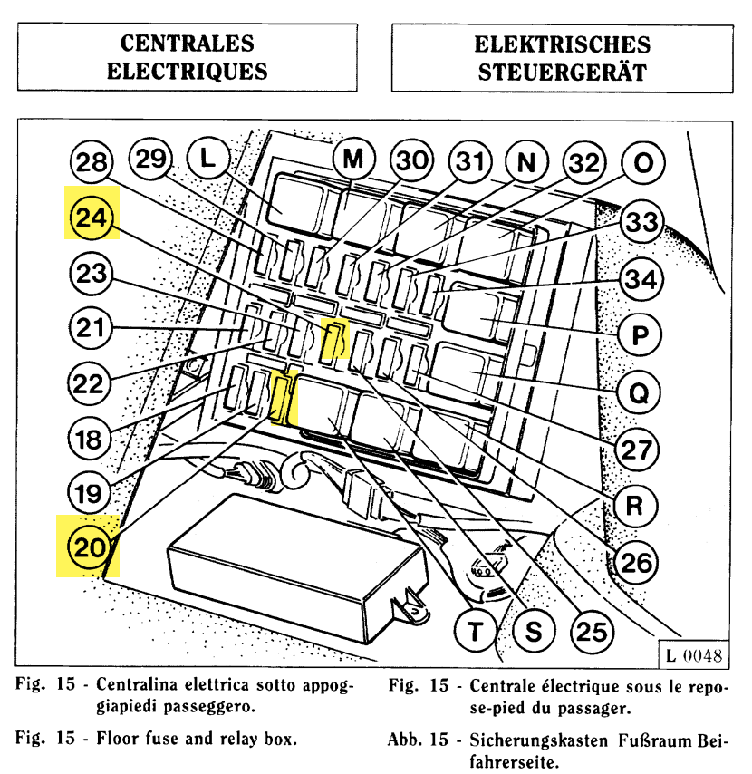
In Section L – Electrical System page L21 of the owner’s manual you will find a diagram of the fuse box layout:

If you look at the legend you’ll see:

that:

20 = RH radiator fan

24 = LH radiator fan

Thus, they are here:


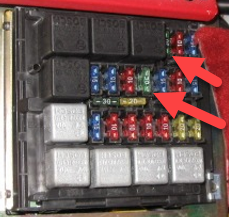
The fuse box location is in the front of the foot well on the passenger side, which you access from inside the car. An old photo I have is:
which looks a bit strange compared the owner’s manual but that could be because my car is Australian delivered. If you look carefully you can line up the layout (in my picture there are 3 x relays at the top, while the owner’s manual has the same 3 at the bottom).

You can also pick the radiator fuses because they are larger (initially 30A but now 40A) that any others. I’ll have to get a better picture at some stage.

So if your F355 is getting overly hot when stuck in traffic for example, first step is to peel back the front all of the passengers foot well and check that the radiator fuses are not blown. They were originally 30A but have been upgraded to 40A as the ‘unofficial’ fix I was told. Main point, is I now carry some spares, just in case and now I also know where they are if they need to be replaced!

Sprung

image

image

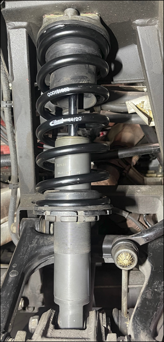
As you can see the new springs are now in place on the car.

Here’s the difference between the old and new springs from the front of the car.

image

The older spring is on the left in the above picture.

I can also attest to the fact that ride is much better. The car doesn’t ‘crash’ into bumps anymore, it takes them in its stride. However, it does now appear that the suspension warning light likes to come on regularly. Let’s see what time bring on that one.

I’m looking forward to taking the car out for a spin on the weekend through a few ‘twisties’ to see what the handling is like. The ride height has also been raised a bit, hopefully to overcome it smacking it’s nose.

image 

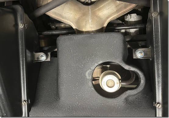
I am also pleased to say that the heat shield over the exhaust was also cosmetically repaired as seen above. It was always an annoying eye sore when I looked at the engine. Now, no more! Yeah.

Also, one of my cooling fans had a blown fuse, which sort of explained why the car almost overheated in traffic on the way to get serviced. The fix is just to install upgraded fuses. Glad, that was checked and resolved. Would not have been nice to overheat in traffic again thanks to a blown fuse.

There still remain some outstanding items to address:

– the A/C mixing flap still doesn’t work, even though I sourced a replacement COG for it. Possibly a main controller unit issue but we’ll need a spare one of those to test before we can be sure.

– the suspension warning light seems to want to come on during start up and at random on a drive. Let’s give that one some time and see if there is pattern to why it’s doing that.

– even though the EVAP system has been thoroughly checked and a new charcoal cannister installed the car still smells a little ‘fuely’ after a drive. It has always been like that but I would have thought that a new charcoal cannister would have rectified that issue. I’ll need to do some more research to see what is normal when it comes to fuel smells after a drive.

– after the interior refurbished I can feel an airflow just below the handle of the drivers door. Seems to be coming from outside the car. Not a huge issue and I’ll need to have a closer look when a get a chance.
– as mentioned before the valve guides are going to need doing. The aim will be to take car of that around mid year.

However, all the belts and fluids have been done as well as the hydraulic tensioners, spark plugs, etc. as part of the engine out service. The ride feels much better now, so I just need to wait for the weekend to see what the handling is truly like.

The engine is out

image

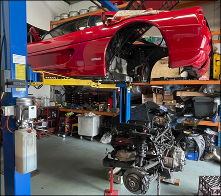
The F355 is in for it’s annual service and this one will require an engine out and belt change amongst many other things. As you can see above, indeed the engine is now out.

image

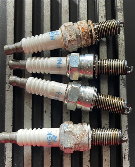
Interestingly, there is some major corrosion present on the outside parts of the plugs as you can see above for cylinders 1 – 4

image

and cylinders 5 – 8, above. This is strange given that the corrosion is on the part of the plugs that is outside the cylinder! It is also interesting that two plugs on either side are largely unaffected while two others are quite corroded. The part that goes inside the cylinder is fine. This kind of suggests that somehow water has been trapped in and around the plugs for some reason.

Next was a leak down test on all the cylinders.

image

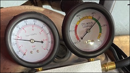
Most of cylinder are good, like above, except:

image

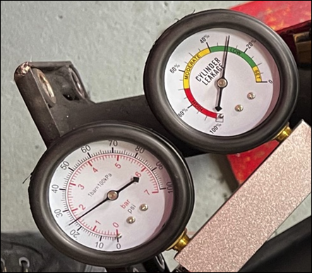
Cylinder 4 at 30% and

image

and Cylinder 3 also at 30%.

This is a loss of power in those cylinders and is typically caused by wear on the valve guides. Getting that fixed is a major job for the future but it good to have these readings as a benchmark.

image

No signs of issues with the evap system but got a replacement charcoal cannister just in case.

Still more work to be done but the corrosion on the spark plugs is a bit of a mystery and the valve guides will need replacing down the track as well.

Let’s wait and see what else is found.

Service time

image

It’s that time of the year again when the F355 goes in for it’s annual service. Apart from the normal rego check and fluids, this one will also be an engine out and belt change.

To further add to this I’m also getting the suspension ‘renewed’ as well as hopefully the evap issues sorted amongst a host of other ‘smaller’ items that need attention.

While taking the car to Racing Red I got caught up in some heavy Monday morning traffic, which didn’t help my stress levels at all! At one point the water temperature got to 120 degrees (130 being the max) and the oil temperature almost reached 100 degrees. I was worried that I’d need to pull over. Seems like the cooling fans weren’t working for some reason?? Luckily, I managed to get the car to its destination but cooling fan operation maybe something else that needs checking as well it seems.

I’ll report back on the progress but this one is going to be a big one, but it is all necessary and hopefully will sort out all the recent issues with the car, especially the ‘chuggs’.

More soon. 

The Cog is wrong

I have finally managed to get around to printing the replacement cog:

Gear of misfortune

using nylon, but I’ve discovered an issue with the 3D model I’m using.

clip_image001

If you look closely at the original cog you see that teeth rise from left to right.

image

but the model I was given (above) has the teeth falling from left to rise. That is, in the opposite direction to the original. This would explain the friction I’m getting when I insert this new wheel.

I got this model from the people I sent it originally to, who failed to produce a suitable result. It now looks like I’ll need to model the whole thing myself from scratch. Painful.

The cog I have printed using the model with the wrong teeth does work but it is a tight and doesn’t move as freely as cog with the correct teeth.

Back to the drawing board.


Hooking new blades

image

Recently, I started hearing an annoying rubbing sound at the top of my wiper blade travel on the passenger side. Upon closer inspection I found that the blade had detached from the arm as shown above. Thus, when the blade changed direction at the top of its arc, the rubber was dragging on the windscreen.

For replacements, I decided to go with a set of Braumach. These are very different from the existing blades and are basically composed of a long floppy arm that wipes the windscreen. Given that, even when new, the existing blades were not great at keeping the screen clear, I thought I’d give these new ones a go.

image

image

To get the original blades off you’ll find a small lever near the pivot point as shown above. When you push or pinch it towards the blade is probably a better description, you will be able to slide the whole wiper assembly off by moving it towards the windscreen. You may need to slide the water delivery pipe down a little to permit this.

image

Removing the blade assembly will reveal a hook as shown above, onto which the assembly attaches. This is why the blade assembly slides off towards the windscreen initially.

You simply hook the replacement wipers in place on the wiper arm and use their locking mechanism to secure them. Pretty easy. I also noted that the actual rubber on the new blades had a plastic cover which also needs to be removed.

With both wipers back in place with new blades, I took the old blades to the local auto accessories shop and got new rubber blades for that assembly as well. These needs to be fitted and then trimmed to suit. I decided to leave the old blades off but keep them stored, and see how these new ones go. The new ones look more like the wipers on modern cars, such as my daily drive, so I’ll be interested to see how they perform in the wet compared to the original ones.

So a pretty painless process overall and hopefully my blades no longer make an annoying noise at the top of their travel and they provide better visibility.

Solving the ‘chugs’

I’ve been battling a ‘chugging’ issue at warm start up now for almost 12 months, without a great deal of success. The last episode was:

It’s still an issue

After all the engine checks, by two mechanics, i still get the issue. Not all the time, but often enough to be really annoying. Problem is, I can’t replicate it on demand. That makes it extremely tough to troubleshoot.

After the engine check failed to resolve the issue completely, the focus turned to perhaps the problems being related to the third party alarm I have. As I understand things, the 2.7 355’s didn’t come with a factory alarm, while the 5.2’s did.

So I got a clever auto electrician/alarm guy to have a look and he is very confident that it is not the alarm. However, he said that it sounds like the evap system to him!

image

image

The evap system is designed to capture fuel vapour and store it in a charcoal canister to be burnt off later. As you can see from the above diagram, the system has 2 x solenoids, 2 x valves, hoses and the charcoal canister.

image

image

Looking at my car I see:

image

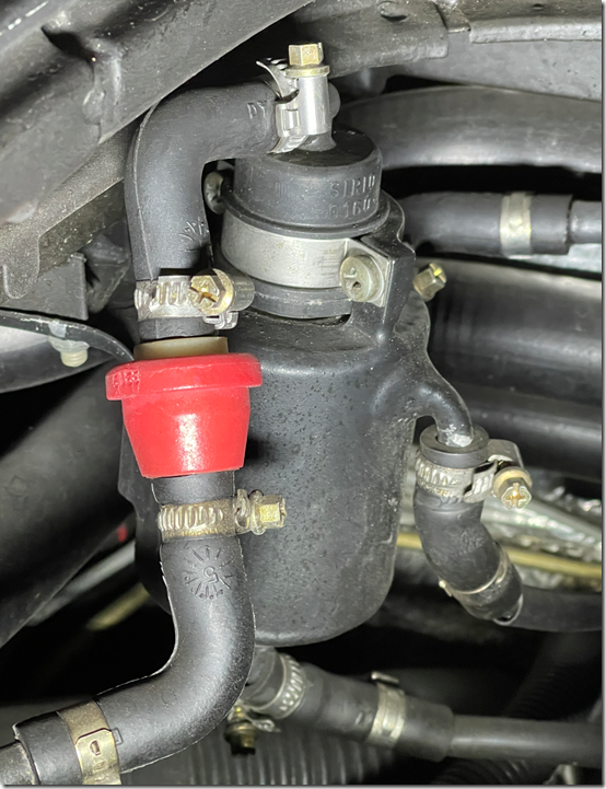
The vapour separator,

image

image

and the bottom of the charcoal canister, which all look good visually. The charcoal canister is housed inside a fibreglass housing.

The suggestion is that if the ‘chugs’ re-appear I should stop the car, take the fuel cap off to let the pressure equalise, restart the car and see if the ‘chugs’ are still evident. If so, that kind of confirms that I have an evap issue.

Typically, the ‘chugs’ only happen after I have been for a long drive, fill the car with fuel and then try and restart it. I’ve had the ‘chugs’ return after paying for fuel and also when I put the car away. The only real commonality is the car needs to be warm for the ‘chugs’ to appear.

Armed with this new method of dealing with the ‘chugs’, of course, nothing happened on my drive and refuel today. However, at least I’m now armed with a simple action that may over come the issue. If that in fact does, then looks like I need to focus my attention on the evap system to find the source of the issue.

Until that happens and I can confirm that it is indeed the evap system causing my issue, I’ll continue to reach troubleshooting techniques. Interestingly, I can’t find a lot about this issue on the Internet. It does seem to be something rare, but then my mother always told me I was special!

Project COG is back in business

Many moons ago a cog in the AC timing actuator failed as I detailed here:

Gear of misfortune

I thought it would be easy enough to get a 3D printed version as a replacement. Oh, how wrong I was. I tried some trusted contacts who were in the 3D printing industry. They referred me onto a number of businesses who unable to print a cog for me.

After more than 2 years trying to get a commercial 3D printing business to print a replacement cog for me, I decided that the only way it was going to happen was if I did it myself. Thus, began another long quest to learn about 3D printing.

A few weeks back my 3D printer selection arrived. After assembling it and doing some test prints, I turned my attention to the real reason for my purchase, to print a simple cog!

Attempt 1

clip_image002

As you can see from the above, this attempt didn’t go well. The issue was the fact that due to the small size of the cog the print lifts from the bed.

Attempt 2

clip_image002[6]

Things are looking better now after some adjustments to the printing process. I can at least see that it is starting to look like a cog, but again the print is detaching from the bed. More adjustments.

Attempt 3

image

YEAH BABY! We have a winner. As you can see the print completed successfully. I needed to some minor clean up on the finished product but I tested it in the Timing Actuator and it seems to work fine.

Oh man, has this been a long (and expensive journey) all to get a replacement for this tiny cog! However, there are a few minor tweaks I need to make to the model so it needs less clean up after printing but I don’t expect that to be too hard. It’ll also be a good way to learn more about the 3D modelling process.

I can now finally say that I have the ability to produce a solution for the 63307100 Timing Actuator gear failing from about two years ago! Even though I do have a number of cogs made by others that work the one I just printed myself now holds pride of place.

During this process, a few readers of this blog contacted me about obtaining a replacement for themselves if I managed to produce them. Well I have and you are welcome to reply to this post, or contact me directly via email and I’ll send you what I have made. Note, that I am still tweaking as we speak and I have not yet actually put the cog into the car so I can’t guarantee that it works on the road, but I’m pretty confident it will. But, if you want to try it and let me know if it indeed does work, contact me a I’ll send you a print.

Hopefully, after a few adjustments I can offer these to people who experience the same issues.